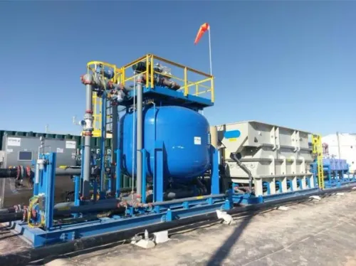
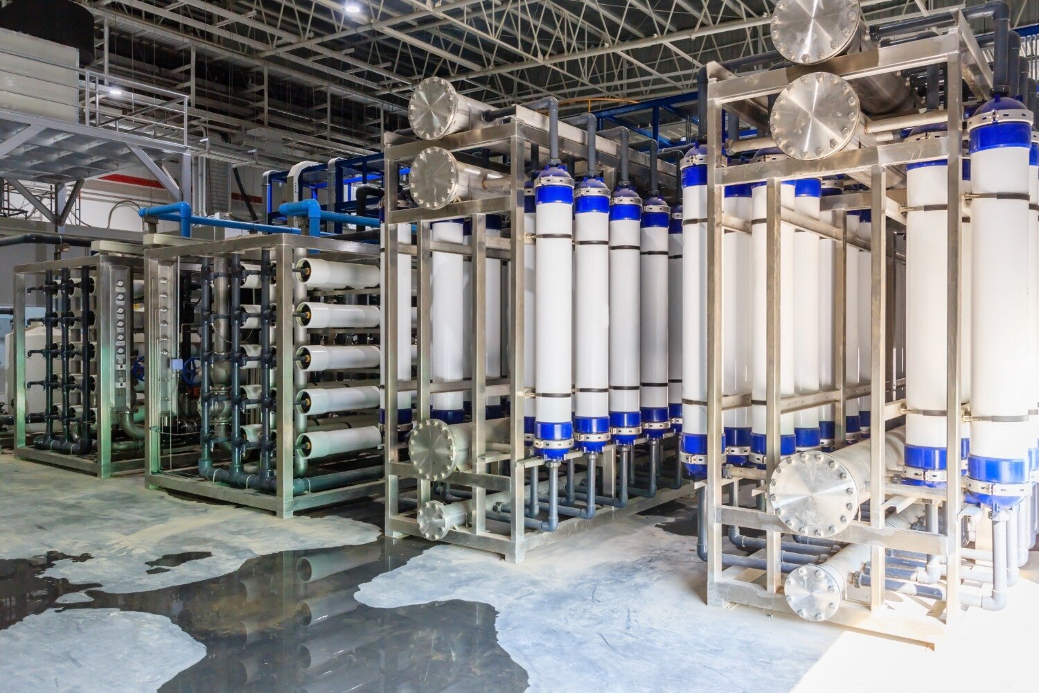
A UF skid rated only for the raw-water pump may fail to deliver the permeate volume your factory needs after backwashing, cleaning, standby allowance and seasonal feed changes. You will be able to calculate the required capacity, select the right train arrangement and specify pretreatment and performance guarantees for your Nagpur site.
Key takeaways
- Size UF capacity from net permeate demand and operating hours.
- Include backwash, chemically enhanced cleaning and reject flows in the water balance.
- Match pretreatment to suspended solids, turbidity, oil, hardness and biological load.
- Compare guarantees for flux, recovery, filtrate quality, controls and local service.
Calculate UF Capacity From Net Permeate Demand
Size the UF skid from net permeate demand, not the raw-water pump rating. Start with:
Required net permeate flow (m³/h) = daily permeate demand (m³/day) ÷ planned UF operating hours (h/day).
For example, 500 m³/day produced over 20 hours requires 25 m³/h of net permeate. A nominal 25 m³/h skid will undersize the UF plant size for an industrial facility in Nagpur because it leaves no capacity for lost production time.
Adjust the result for:
- The measured peak hourly demand, including batch or shift-start drawdown
- Backwash time
- Chemical-enhanced cleaning and routine maintenance downtime
- A standby train or spare membrane area for uninterrupted production
If backwash and cleaning reduce availability to 90%, the 25 m³/h requirement becomes 27.8 m³/h before peak-demand and standby allowances. Round the selected capacity only after applying both allowances. State whether the quoted flow is gross membrane flow or guaranteed net permeate flow.
Recovery converts permeate demand into feed demand. At 80% recovery, producing 500 m³/day of permeate requires 625 m³/day of feed and creates 125 m³/day of reject; size equalization and reject handling for that stream.
Include the minimum feed-water temperature in the flux calculation because colder water has higher viscosity and produces less permeate at the same transmembrane pressure.
For UF plant capacity selection, require the supplier to guarantee net flow, recovery, permeate turbidity and cleaning frequency at defined feed limits—not merely membrane area or commissioning-day flow.
Match Pretreatment and Water Balance to the Feed
Do not size an ultrafiltration plant in Nagpur from one clear-water sample. Test each feed source and season separately, including monsoon conditions, for turbidity, TSS, SDI or another fouling indicator, hardness, alkalinity, iron, manganese, oil and grease, TOC or COD, and microbiology.
State the minimum feed temperature used for flux calculations: colder water is more viscous, so it produces less permeate at the same transmembrane pressure.
Pretreatment must protect the selected modules from the actual solids and contaminants:
- Set the maximum particle size entering the modules.
- Select screens, strainers or cartridge filters against that limit.
- Add oil removal or coagulation when oil, grease, high color or biological solids exceed the membrane’s feed limits.
- Increase cleaning provision and membrane area when seasonal fouling reduces sustainable flux.
The water balance must show every stream, not just permeate and raw-water feed:
- Raw-water feed to the UF system
- Net permeate sent to production
- Backwash and air-scour drain flow
- Chemically enhanced cleaning or CIP waste
- Concentrate, bleed or continuous drain flow
These losses determine raw-water pump capacity, equalization-tank volume and waste-treatment duty. A plant that delivers 20 m³/h of permeate can require substantially more feed flow once backwash and cleaning losses are included.
Size from net permeate at the stated minimum temperature, peak demand and available operating hours, then verify recovery and reject handling against measured feed quality rather than using a generic micron rating or membrane-area estimate.
Choose the UF Operating Mode and Physical Layout
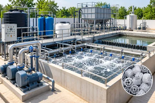
Dead-end operation with periodic backwash suits clarified industrial water: feed passes once through hollow-fibre membranes, then air scour and backwash remove the cake. Use crossflow when suspended solids, colour or biological loading remains high; continuous concentrate circulation controls fouling but increases pump energy and reject volume.
| Option | Membrane configuration and operating mode | Best fit |
|---|---|---|
| Dead-end | Inside-out hollow fibre with backwash and air scour | Low-turbidity, well-pretreated process water |
| Crossflow | Inside-out hollow fibre with continuous concentrate circulation | Variable solids or difficult-to-filter industrial feed |
| Submerged | Outside-in hollow fibre in an aerated tank | Large biological or tertiary-treatment streams with space for an open basin |
| Flat-sheet | Immersed flat-sheet modules with air scouring | High-fouling duties where robust cleaning matters more than compactness |
Do not place any UF mode directly after oily wastewater, sludge or a chemical shock. Install screening, equalization and oil separation first; add coagulation or biological treatment when the feed requires it.
A pilot or comparable-feed trial is essential for high colour, oil, biological solids or unusual chemical exposure because membrane area alone cannot predict stable performance.
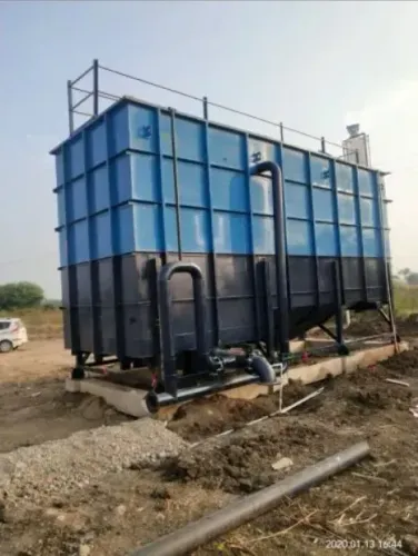
Use parallel trains rather than one oversized skid. Isolate one train for cleaning or repair while others run, and require the supplier to state permeate flow with one train unavailable.
The design must also declare flux at the minimum feed-water temperature, plus CIP tank volume, chemical limits, circulation flow and a controlled destination for acidic, alkaline or oxidizing cleaning waste.
Work Through a Multi-Shift Example Without Oversizing
A three-train arrangement of 3 × 13 m³/h net permeate capacity fits a factory whose demand rises from 180 to 500 m³/day across one, two and three shifts. With 20 planned UF operating hours per day, the required rates are:
| Shift pattern | Daily permeate demand | Required net rate at 20 hours |
|---|---|---|
| One shift | 180 m³/day | 9 m³/h |
| Two shifts | 350 m³/day | 17.5 m³/h |
| Three shifts | 500 m³/day | 25 m³/h |
Run one train during the one-shift schedule, two during the two-shift schedule and all three during the three-shift schedule. If one train is isolated for chemically enhanced cleaning or membrane repair, the remaining two still provide 26 m³/h, covering the 25 m³/h three-shift requirement.
This example treats 13 m³/h per train as net design output after backwash and cleaning losses, not as the membrane’s maximum instantaneous flux. Confirm that value against feed turbidity, colloids, oil, temperature and the selected operating mode; use the minimum design feed-water temperature, not average Nagpur conditions.
For UF plant capacity selection, also test the highest batch or hourly demand. A 500 m³/day total does not protect you from a 30 m³/h process draw during a short production window. Add storage or increase train capacity if that peak cannot be supplied from the permeate tank.
The supplier’s proposal should show flow with one train unavailable, not only the full nameplate figure.
Specify Guarantees, Controls and Local Support Before Purchase
A quoted capacity is not a guarantee unless it states net permeate production at the design feed limits, minimum feed temperature, peak demand, backwash downtime, chemical cleaning downtime and standby arrangement. Reject any figure based only on the raw-water pump rating.
1. Require a signed performance schedule stating permeate flow, recovery, turbidity, normalized permeability or TMP trend, chemical consumption, backwash frequency and cleaning frequency. Define the test period and failure remedy.
2. Record the feed envelope: turbidity, suspended solids, oil, colour, pH, temperature, oxidant exposure and biological load. For variable effluent, demand a pilot, site trial or documented reference using comparable water; membrane area alone cannot prove performance.
3. Specify PLC controls for automatic filtration, backwash and chemical-enhanced cleaning, with flow, pressure, TMP, tank level, turbidity and high-pressure alarms. Ask for trend logs, alarm history, manual overrides and interlocks that prevent dry running or chemical mixing.
4. Put the cleaning-in-place design in the purchase order: tank volume, circulation flow, chemical concentrations, temperature limits, duration, membrane compatibility, neutralisation and disposal route. Untreated cleaning waste can upset a biological plant.
5. Obtain commissioning, operator training, critical-spares availability and a named local response contact from the UF plant manufacturer in Nagpur. S K ENTERPRISES can be evaluated on those deliverables, not only on whether its industrial UF water treatment plant starts on commissioning day.
Related product
 | ADVANCE TREATMENT ULTRAFILTRATION PLANT (UF PLANT) An Ultrafiltration (UF) plant process is a pressure-driven, membrane-based separation technique (pore sizes 0.01–0.1 microns) that removes suspended... View product → |
Frequently asked questions
How do you calculate UF plant capacity for an industrial facility?
Divide daily net permeate demand by planned operating hours, then account for backwash, chemically enhanced cleaning, downtime and design margin.
What pretreatment does an industrial UF plant need?
Select pretreatment from the feed analysis, including screening, clarification or media filtration for solids, oil removal, hardness control and biological protection where required.
Which UF operating mode and layout should you choose?
Choose dead-end or cross-flow operation and the physical layout from feed solids, cleaning frequency, available floor area, maintenance access and required continuity across shifts.
What should an UF plant guarantee include before purchase?
Put permeate flow, turbidity, suspended solids, recovery, operating flux, cleaning chemicals, controls, testing procedures and local service responsibilities in the purchase specification.
Keywords